The Bus Stop Bus
The bus
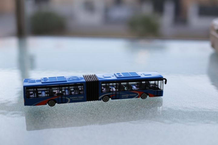
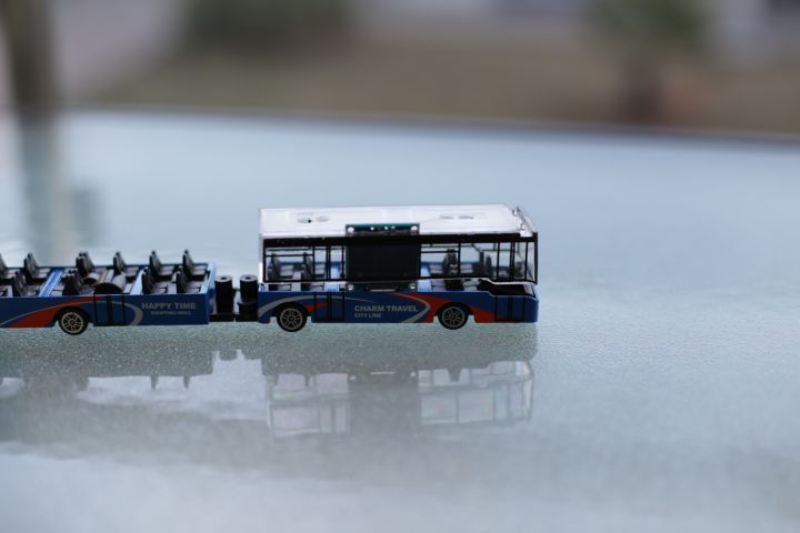
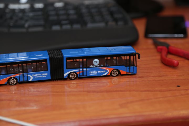
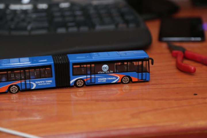
First of all, I needed a bus! You can't make a bus station bus without a bus, so I took a trip to my local toy store and got the beautiful piece of Chinese crap that's pictured to the right for a whole $3. It's made out of metal and plastic, which makes it very resistant to collisions and not too bad-looking. It even includes the usual Chinglish "Happy time shopping mall" and "Charm travel city line" that are the sine qua non of Chinese-manufactured toys.
Please excuse the photos, by the way, as I took them over several days, in several locations and while working on the build, so they couldn't be as nice-looking as I would have liked.
All in all, this is a magnificent specimen, and I was very happy with my find. An added bonus was that the 0.96" OLED screen I got from eBay fits perfectly through the windows, so it's not going to look weird or cut any pixels off.
The screen
Looking at the bus, I figured that the best place to put the screen is between two vertical lines of "window" paint. As I mentioned earlier, the screen was the perfect size to fit this bus, both horizontally and vertically, so it was serendipity.
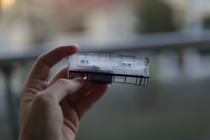
Due to the way the plastic window bit sat below the metal roof, Dremeling a slot into the top of the plastic provided a natural place for the top of the screen to be inserted into, holding it firmly in place and raising it enough to align it properly with the window, hiding the non-screen parts. Yes, I did really luck out with the screen/bus combination.
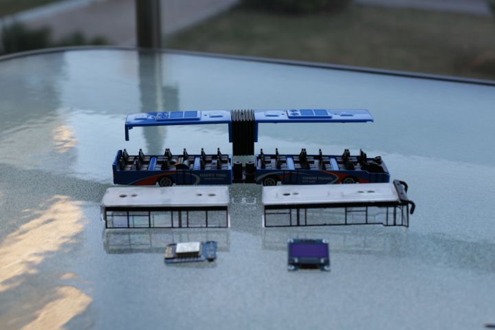
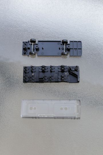
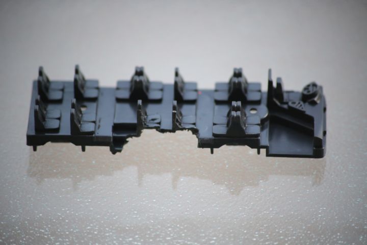
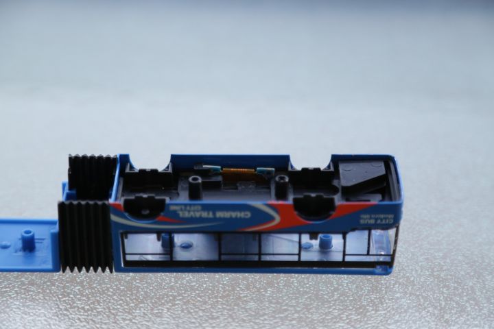
On the bottom side, the bus had rows of plastic seats, which you can see in the photos. These seats were originally too high to allow the screen to pass between them, but carving a small piece with the rotary tool allowed the screen to be sandwiched between the wall/windows and the seats.
Instead of carving the seats down all the way, I left a little piece of plastic at the bottom so the screen wouldn't drop down and get out of the slot at the top. This way, the screen is perfectly held between the roof of the bus, through the slot, and the seats at the bottom. This step might have been unnecessary, as I doubt there's much clearance between the seats and the floor, but it's working well, so why change it?
The end result is basically perfect. The top of the screen was sticking out a bit too much, and I was worried that I'd have to cut some of the top off, but it turned out well. The bottom is also not flush with the seats, but that's because I made some adjustments to lower the screen even more after I took the photo.
I think the roof of the bus actually pushes the screen down a bit when screwed on properly, so cutting the top of the screen off would make it fit better, but the result looks good as it is, so I left it. The top is also where the connectors are, and I didn't want to risk any electrical problems with contacts touching one another or conducting through the metal roof.
The electronics
For the innards of the bus I chose the 0.96" OLED display and the WeMos D1 mini (a small board that's based on the ESP8266 and includes convenient components for working with it) to drive it.
I like the WeMos a lot in general, but I ended up not choosing it for this build. Even though it's about the size of two postage stamps, it turned out to be too big to fit in the bus, another poignant indicator of the growing rates of obesity in this country. The only breakout that's small enough to fit in the box without requiring extensive cuts is, as luck would have it, my very own (and appropriately named, it seems), tiny ESP8266 breakout.
The microcontroller
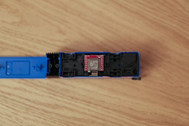
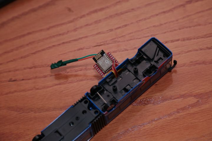
Since the screen was working well, the next step was to install the microcontroller. As I said above, I initially chose the WeMos D1 Mini, my ESP8266-based breakout of choice, but when I tried to fit it in the floor of the bus, I discovered it was a bit too wide to fit in the sides and too long to fit between the two screws.
Luckily, I had already designed the smallest ESP8266 breakout in existence, so I tried that. It ended up fitting more or less exactly, with a bit of room to spare, in both dimensions. It's not as convenient as the WeMos, in that it doesn't include a USB connector or a USB serial chip, so it's less convenient to flash, but thanks to the ESP8266's WiFi connection, I can send new updates to it wirelessly. I have also written an HTTP firmware upgrade server, which allows all of my projects to look for and apply the latest updates to themselves automatically.
In case you didn't know, "flashing" means upgrading the software (otherwise known as "firmware") on the microcontroller. Whenever you want to add a new feature or fix a problem, you need to flash the new version of the software onto the ESP8266, which normally requires connecting a cable to it, whose other end usually goes to the computer's USB port.Powering everything
Absolute power corrupts absolutely, as they say, but a lack of power doth butter no parsnips, so I had to find an elegant way to power the whole thing. Since my breakout board has a voltage converter, it accepts a wide range of voltages, 5 Volts, 5.1 Volts, you name it.
A very easy and disgusting way to get approximately 5 Volts, but sometimes up to 100 Volts, is to use a cheap Chinese phone charger. These days, since everything is made in China, the qualifying adjective "Chinese" is probably redundant, but I use it to instill the fear of electrocution in your hearts. Anyway, wiring a USB connector to the board was quick and easy, and half the power issue was solved.
Making it look pretty (or at least non-ugly), though, was another matter. The only plastic parts of the bus are the windows, and the rest is metal, so it's very hard to shape with the rotary tool. Luckily, this bus wouldn't be carrying passengers, so it didn't need all of its wheels, and now you probably see where I'm going with this.
I quickly cut one of the axles off, and replaced the wheel with the USB connector, as you can see in the photo on the right. The connector is on the side opposite the screen, so it's invisible from the front, and is very sturdy because the connector is sandwiched between the two plastic pieces that hold the wheel axles, making sure it won't get ripped off during cable insertions and removals.
This is doubly important because the other side of the USB connector has very thin pins that are meant to be soldered to printed boards, but I only had wires, so excessive jiggling can easily break the solder and disconnect the cable.
After tidying up the connector and screwing everything back in place, the hard part was done! Time to move on to the soft part.
The software
The software for the bus doesn't really do a whole lot, as the parsing doesn't happen on the bus itself. I use my municipal transit authority's website to get information for the bus stop outside my apartment, which is done by a Python script that runs on my home server and scrapes the site and sends the times to an MQTT queue I have running on that same server.
The bus itself listens to a channel on the MQTT server, waiting for a new set of times to be published. This happens twice a minute, so the bus takes the published times and displays them on the screen.
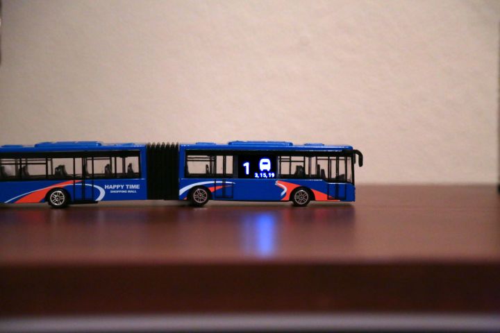
You can see the actual screen output in the photo on the right. All the numbers are minutes until another bus arrives (all the buses going past my apartment run the same route, so the only information I need is minutes), and the ETA of the next bus is shown in a big font on the left. Times for subsequent buses are shown in a smaller font on the bottom of the screen, and I thought it would be nice to throw a jaunty icon of a bus there (taken from FontAwesome), just in case the huge bus around the screen wasn't enough of a hint that these are bus arrival times.
I used the SSD1306 library to drive the display, along with the excellent SSD1306 font converter for the numbers font. Drawing everything was really straightforward, as the library is quite easy and powerful. Here's the code that produces the output shown in the photo on the right:
display.setFont(Roboto_53);
display.setTextAlignment(TEXT_ALIGN_CENTER);
display.drawString(32, 1, earliest);

display.setFont(Roboto_18);
display.setTextAlignment(TEXT_ALIGN_RIGHT);
display.drawString(128, 45, upcoming);

display.drawXbm(76, 0, bus_width, bus_height, bus_bits);
Thankfully, the data is pretty accurate, which makes this project a very useful indicator of when to leave the house in time to catch the bus. It also doubles as a passable ornament for the bookshelf, and a conversation piece for all the visitors who wonder what the hell a bus needs with a screen that shows numbers. Apparently, we Greeks are easily dazzled by mystical screens with numbers and the iPhone 7, despite literally having discovered electricity.
Epilogue
That's it! This build was pretty quick and easy, and a lot of fun. It's also one of the least useless things I've ever made, which saddens me, but at least now I can miss the bus while remaining fully aware of my perpetual tardiness. I hope you enjoyed reading about this build as much as I enjoyed that Mars bar I stole from that preschooler (free stuff does taste better!).
If you have any feedback, or interesting builds of your own, please leave a comment below or tweet to me, I always enjoy hearing from you.
Thank you!
