Light painting with drones
Project in progress
Initial, manual attempts
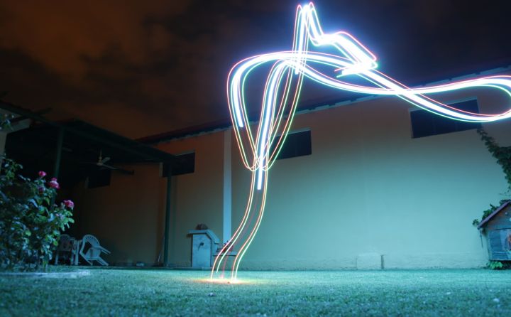
At first, I connected some WS2818 LEDs to the bottom of my quadcopter and configured it so I can turn them on and off from my remote controller. I went out to the yard for a quick test, and tried to manually draw a square in the air. The photo above is that square.
Indeed, it looks almost, but not quite, entirely unlike a square, and that's because precisely controlling a quadcopter manually is impossible, at least for me. This told me in no uncertain terms that I would need to add GPS to it and also possibly abandon this project altogether. I decided to only listen to half of my instinct, and ordered a GPS unit, then a second GPS unit, another flight controller, and also enough other parts to make an airplane drone, for some reason.
I also ordered a third flight controller, identical to the one on my quadcopter, but with a barometer and magnetometer. These will help the quad know how high it is and which way it's facing with better accuracy, so it seemed like a worthwhile investment, insofar as anything I do is a worthwhile investment, i.e. not at all.
GPS unit arrives
After a few short weeks, my GPS unit arrived. I quickly opened my quad up, sticky-taped the GPS on the outside of the body, and tried to figure out where to connect it to my flight controller. Unfortunately, the only available port required a connector I didn't have and couldn't find anywhere outside of China, so my enthusiasm quickly turned into a raging depression when I realized that I'd have to wait three more weeks for the next step.
Regardless, I placed a fourth order for these connectors, hoping that this time I had actually ordered the right ones, unlike the previous three.
Testing with the closed-source drone
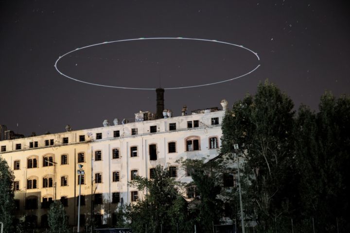
Right in the middle of my planning frenzy, I realized I can just duct-tape a flashlight onto the bottom of the other quad and try that. I took a photo like that with not discouraging results. This is a good plan B, although nobody ever made omelette with a plan B.
The new flight controller arrives
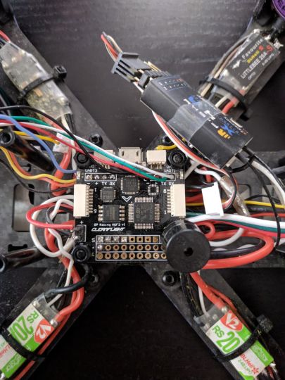
Finally, the copy of the flight controller I already have (plus a barometer and compass) arrived as well, and, would you believe it? It had exactly the connectors I needed! I quickly spent an entire day desoldering the previous connector, figuring out where everything should go and soldering the new one. The GPS module contained a magnetometer (compass), which various people heavily recommended I use because it doesn't get as much interference, since it's farther away from all the electromagnetic fields generated by the internal circuits. I summarily ignored this advice, figuring that accuracy is for chumps and that I don't need professional-level accuracy anyway.
After spending a few more hours figuring out why the GPS module doesn't work, I found a solution and got everything working, at which point I completely stopped touching anything and backed away from the quad. I then very carefully put the body back together, taking extra precaution not to break anything. Naturally, I broke something: The creators of this quad hadn't taken into account the fact that some insane person might want to actually connect something to the connector, and hadn't left enough space, which caused the socket on my brand new controller to break off the pad.
Thankfully, it didn't completely break away, so it still worked, but I'm sure as hell not touching it again. Time to see how/if this thing flies.
Flight tests
I spent a few hours with the drone crashing left and right before I got the settings exactly right so it could finally take off, but it barely managed to fly properly. I decided, with the help of the very helpful people over at the iNav Slack channel that I need to actually use the external magnetometer and that the internal one is trash.
Back to the drawing board, I expertly removed the internal magnetometer from the PCB by pulling it off with some large pliers, and managed to miraculously connect the external one after lots of prayer. Trying another flight, the drone was visibly better at flying, although it still drifted a lot. After asking in the channel about that, and half hoping that in the mean time the quad would somehow get confused enough to fly away and spare me all this pain, I was told that I needed to mount the GPS module as far away from the body as possible.
Mounting the GPS on a mast
Of course, at that point I needed another three-week wait like I needed a very unnecessary thing, and I didn't want to order a mast from China again. Luckily, I am the proud proprietor of a 3D printer. Fun fact: All printers are 3D printers. A 2D printer is a photo of a printer.
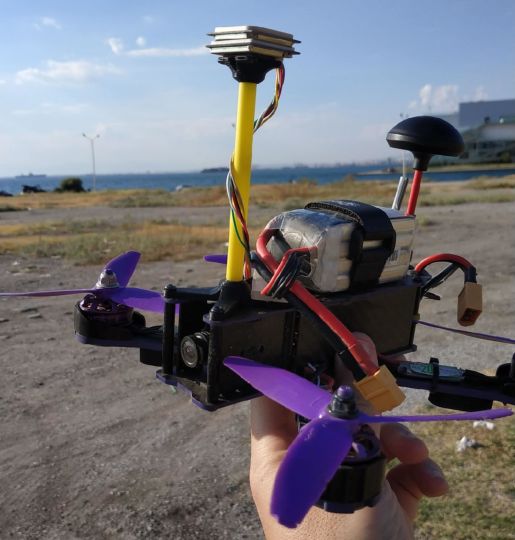
I quickly designed and printed a mast which actually fit quite snugly, and glued the GPS module onto it. This made the quad hold its altitude even better, but of course it still wasn't good enough. I was informed that I should encase my barometer in some soft foam to avoid wind gusts influencing it, and that I needed to tune my PID controller with better values.
Adding WiFi to the quad
Tuning the PID controller was hard, because I knew nothing about PID. However, I knew nothing about everything until I learnt it, so I wasn't going to let this mere lack of knowledge deter me. The more significant problem was that I would need to take the drone out, fly it a bit, see how it flew, then bring it back, land it, connect it to USB, change a value, launch it again, see how it flew, and continue this cycle until the sweet embrace of death freed me.
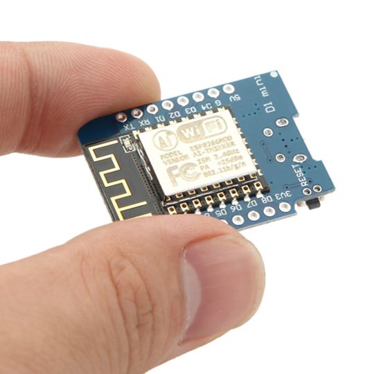
Not willing to go through all this, I went with the second best option: Adding WiFi to the quad so I could connect remotely from my computer or phone. I did this with the help of an ESP8266 with the excellent esp-link firmware, which allowed me to create a virtual serial connection over WiFi. That way, I could change values on the fly, literally, with only a less than 50% chance of the drone crashing to the ground.
Adding a better flashlight to the closed-source drone
In the mean time, I figured I'd add a flashlight to the Xiaomi quadcopter, as it does much better circles and is a bit more stable while controlling (and why not?). I taped a flashlight I had to one of the legs of the drone, but I think it was a bit too heavy, as it caused problems while flying and made the drone wobble so much I was afraid it might crash, so I quickly took that off.
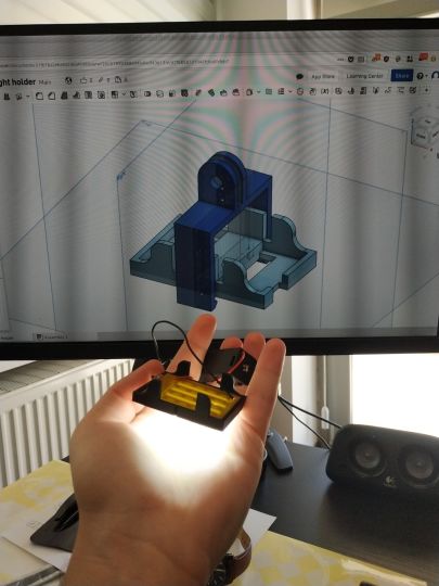
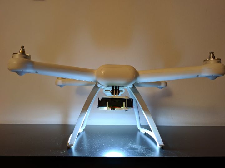
I figured that a better place to mount it would be the camera mount, so I bought a $3 flashlight, took the PCB with the LEDs out and designed a case and mount for it. I connected all the parts up using steel screws and it fit and worked perfectly. The next step was to try to fly the drone.
Unfortunately, the quad kept complaining that the compass fix wasn't good enough.
Fixing the compass issues
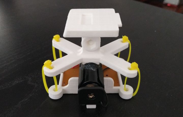
I didn't feel comfortable trying to ignore the compass warnings and try to fly the quad, so I started debugging. Initially I thought that the current going through the battery, wires and LEDs was generating electromagnetic radiation and throwing the compass off, so I designed a different mount that would put more distance between the body of the drone and the circuit.
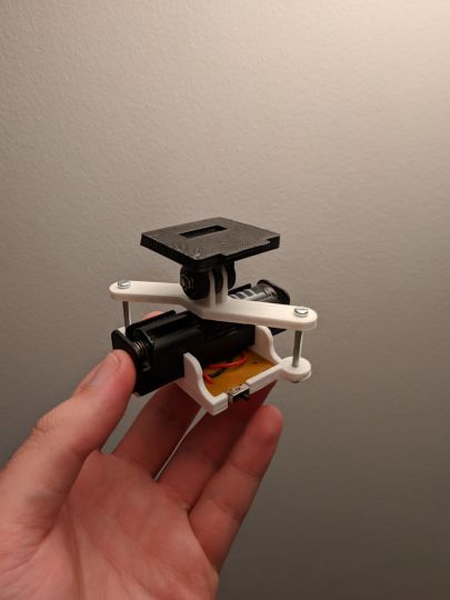
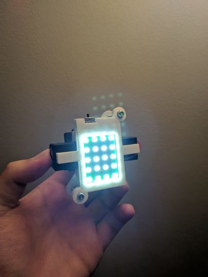
Alas, that didn't work very well either, and someone on the Ardupilot forums gave me advice on the real culprit: The steel screws changed the earth's magnetic fields enough that the compass was getting confused. Realizing that I didn't need the heavy steel screws, and that glue was more than good enough for most things, I replaced the steel screw at the top with cyanoacrylate glue (superglue) and put a 3D-printed plastic pin where the screw was, for good measure. I also replaced the four screws (instead of two in the previous design) with zipties and glued a battery holder onto the top part so the top and bottom parts wouldn't move relative to each other.
I will test the quad and report back!
